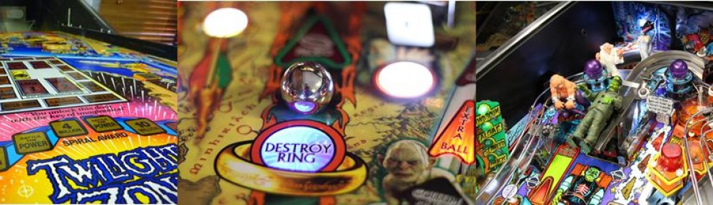
Medieval Madness (MM) is an extremely collectible pinball machine, and a lot of fun to play. They are getting quite expensive nowdays. I’ve always wanted to take on a big pinball challenge, so i am planning on converting another WPC95 (machine that has same cabinet style and boards) machine – NBA Fast Break (NBAFB) into a MM.
I will add to this post over time and i’m not setting myself a time limit for the project, it may well take quite a while, and some of the additions to this page may be a bit all over the place, but i’ll just add things in the order i do them!
A couple of guys in the US have done this project before, and have had another MM to copy off – i’m attempting it without one to copy off, so we will see how i go with it!
OK, this is real, and it is happening. I think its going to be quite the challenge without another MM to copy off, but thats half the fun.
I have to thank Wally from pinside, as he has provided me with a few documents that help out a lot, as well as spending an hour or so chatting with him on skype for other tips and inspiration.
There are a few parts that are a bit difficult to get, but i’m chasing a few avenues for them.
So, i’ve got the MM playfield, NBA FB should turn up in the next day or so, i’ve got around $2000 worth of parts from two Aussie suppliers – both who have been fantastic and very helpful via email and phone. I also bought a lot of metal parts from mantis amusements in the US, and am putting in an order for a lot of general parts/motors/brackets etc from another store in the US right now.
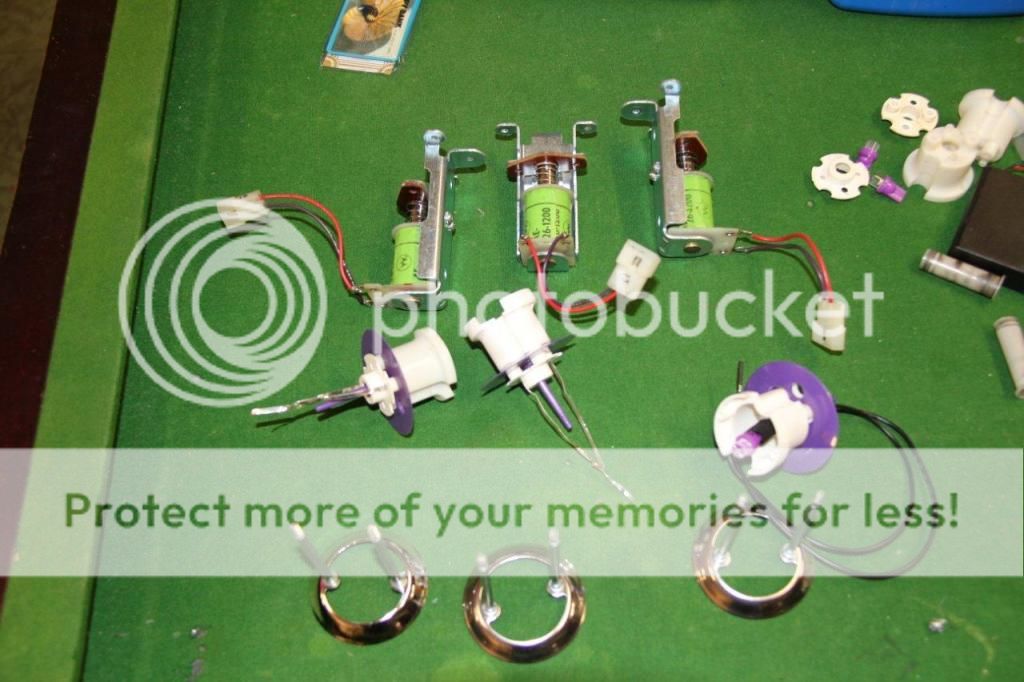
I started tackling a few of the assemblies – a couple of divertors, the trolls, and ball gate actuators. I didn’t complete the trolls as i will prob put LEDs in the eyes, so just quickly put together to ensure i had all the parts. Its amazing how many bits are in these,and you think you will have plenty of spare screws, nuts and washers etc – but i’m stocking up on plenty more of them as i’m running through plenty of them. Its not a hard process, just follow the diagrams in the manual, and hope that you ordered the correct parts!
As we unwrapped the parts to date, the young bloke was pretty excited about the dragon and trolls!

Assembling ball gate actuator

Troll assemblies partially completed

Not sure what i will move to next, probably get the NBA FB and play it for a while, then start pulling it to bits, and maybe start on the wiring harness.
Advice welcomed, or any of the castle bases that are quite tricky to get at the moment!
Got the NBA FB donor machine. I always thought i would play it a bit to see how it was, anyway, after 5 minutes of playing i was too keen to get into starting the conversion..

The NBA is largely in good condition, trough opto boards and 7 opto board was missing, but playfield, ramps and most plastics are in very good condition – if anyone needs any parts, let me know!
The cabinet is pretty solid, will need a few dings and scratches repaired before putting MM decals on, but that is a long way off
Started off by removing the playfield from the machine to start stripping

I started on the underside, and removed each of the wiring harnesses

Started with the coil and flasher harness, and i labelled each plug (or cut wire pair) with a number, this number was then recorded against the NBAFB coil table, so that when i put the harness in MM, i know where that set of wires should go.

Same then with switch and light looms – switches were labelled where they attach to the playfield

The GI and controlled harnesses were all twisted together, so will be a bit of fun getting them apart.
Once all the components off the bottom were removed, all the top side was pulled off. Its amazing how much quicker it is stripping a playfield when you dont take any pictures of where things go!
Parts were then organised into stuff that i would reuse or not. Things like pop bumpers, flipper mechanisms, playfield brackets etc will be totally stripped and cleaned before being reused


Playfield all stripped now

Once the playfield was stripped, i had plenty of hardware bits to start on the new playfield. Also had a massive tangle of wiring from the harnesses. I separated them out into the 4 harnesses, and washed them in the laundry tub with degreaser and nifti. They weren’t filthy, but did have a bit of black gunge that was good to get rid of. After washing, i rinsed lots of times, then left outside in the sun to dry properly. I then stored them away as these will probably be a later job at this stage.
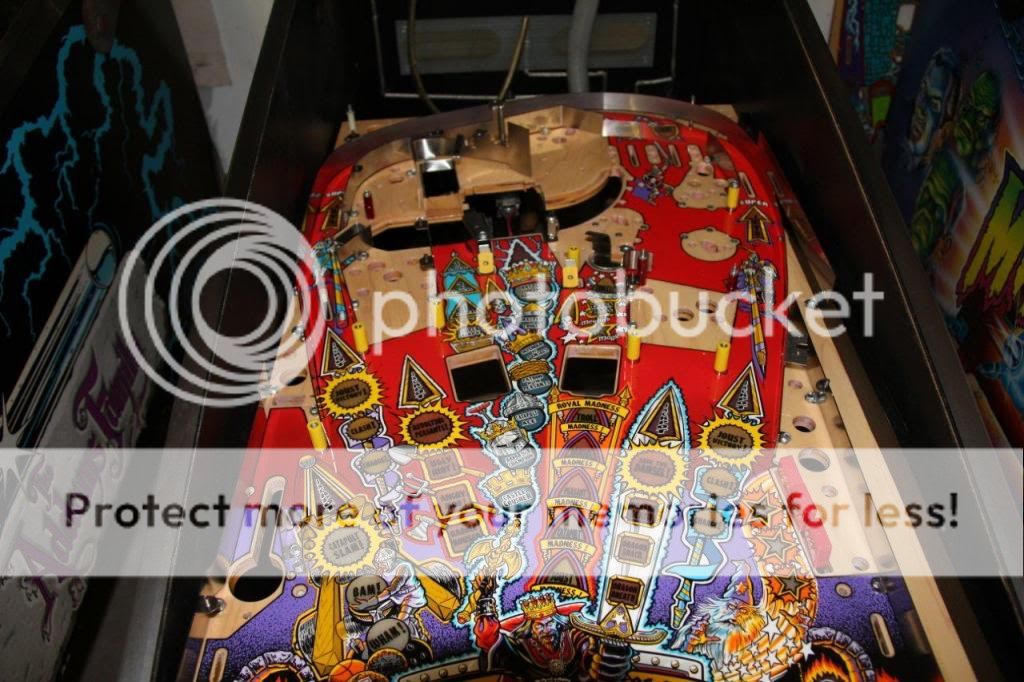
So i had all the T nuts from NBA, and installed them on the MM playfield – the ones on the top side of the playfield were tapped with the hammer to start, then finished using a socket just a bit smaller than the T nut as a drift.
I then installed the timber side rail – cut the NBA one a bit shorter to the correct length, then i put the hinges on underneath the playfield and installed in NBA cabinet. Note that i have also installed the MM roms, so i guess i officially have an NBA Madness now???

I have also started making the backboard. Used 12mm MDF, and got dimensions off Wally who had previously done a conversion – then used the backboard decal to locate the appropriate holes

I’ve installed the Mantis protectors – this Merlin one is a real pain to install, happy of anyone has any tips? Its sitting a few mm proud of the playfield, and needed to be bent to install, i’m assuming installing from underneath is the best – looks like i will have to bend the front lip down, but haven’t worked out the safest way to do that installed without potentially damaging the playfield

Installed the other two Mantis protectors as below – the right larger one was too wide to fit the hole (being a repro playfield) and needed to be bent a fair bit to fit, so it still needs some panel beating to make one side fit a bit more snug – although this will be hidden once the castle is installed.

One thing worth noting now while i remember, is that just going through the process of ordering parts is massive. I have been through the manual 4 or 5 times now and still realising i have missed parts – many that i thought i would be able to grab off NBA, or might have lying around as spares. The manual does not even have many parts listed. For example, the scoop below is listed nowhere in the game manual!!!

And all the tiny nuts, bearings, rods, gears, coil brackets, springs etc that go in each of the various assemblies, all add up in cost, and are a pain to order. Since i do not have the luxury of looking at an existing machine, it adds another challenge to all of this. Reference photos from the net, and that others have given me are a great resource to help out. Of course there are still a few parts that are currently not available, so will be making a few of these up. I should mention at this point that both Wayne and MarkC from Melbourne have been very helpful in purchasing stuff, as well as Tony from pinball shed with a few spares.
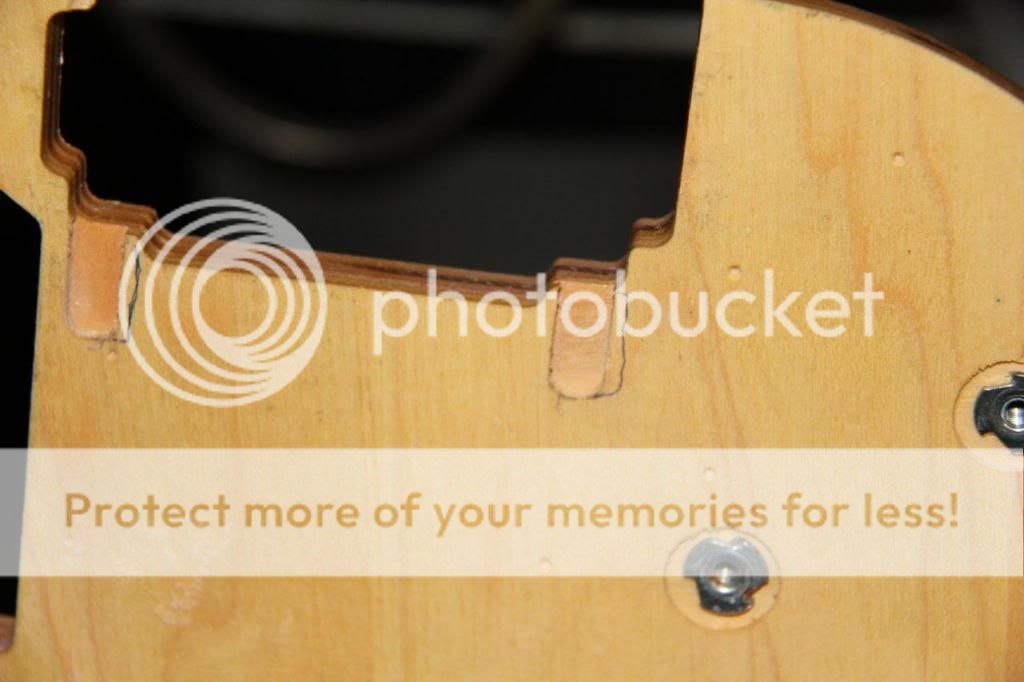
So when i started looking at a few photos on the net, i realised the black side timber on top of the right side of the playfield had some steps cut out to accommodate the large ball guide. If i had a MM here to compare it would be easy, but its all part of the fun trying to work this all out. Looking at a few photos from different angles, i estimate where the steps should be cut out, and took the rail over the the neighbour who has a router mounted on the bench. Cut the step out, and painted black, and everything now installed looks pretty right.
Cutting with the router

I then started making some of the hex posts, i had some measurements from a photo on the net, but looking at the parts manual, i think the lengths listed are more accurate in the manuak (also according to a few other people i emailed). Let me just comment that imperial system is soooo painful. The lengths in the parts manual are listed as decimal imperial….don’t know why the yanks cant figure that metric is so much easier!!! Cut the posts to the correct lenght, then centre punched them, drilled out and tapped the hole to 8-32 size

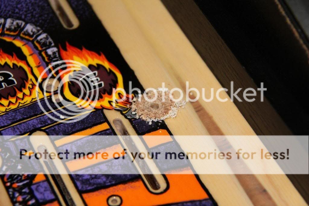
Someone had sent me a link of high end pins youtube video stating how reproduction playfields need to have some modifications. One such was the photo below – i cut a thin slot so the protector can line up correctly with the hole

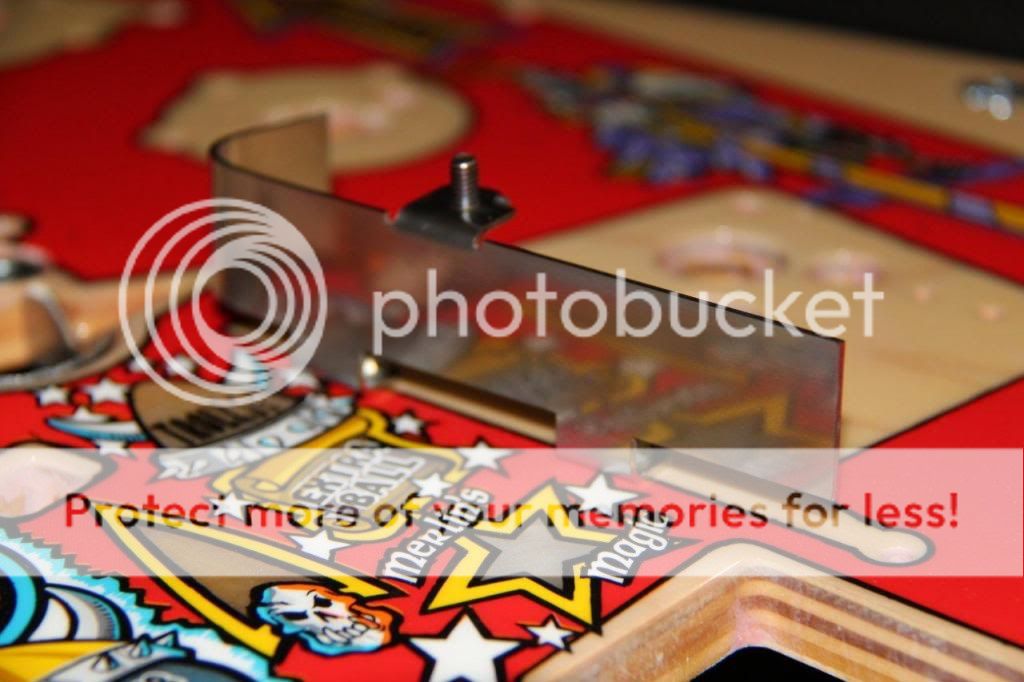
The next nerve racking cuts were made where the gate assembly goes – the slots need to be widened to the right as marked below
Used the dremel to cut a bit wider

One other issue i have just come across is the mantis merlin hole protector actually interferes with the popper that pops the ball out of the merlin hole – happy if anyone has any suggestions to overcome this one?
Then i got all the ball guides. These were laser cut and bent up by a top bloke with a few more metal skills than myself

Start to install the ball guides
Started to install some of the posts, and some of the holes in the playfield were only marked, not drilled. Again, a few nerves and make very sure the drill doesn’t slip when doing this stuff!!!
Again – i don’t have anything to copy off, so just going off photos of where things go, but things are starting to come together a bit now
OK, just to prove this is still ticking along…. I really haven’t done anything for a few months, been too busy with other projects and family, but got a bit inspired yesterday to give it a bit more attention.
Stripped pop bumper bodies from NBA FB, cleaned, and put pretty much all new components in them
When i went to install them, the holes in the playfield were a tiny bit too small to fit the pop bases, so after a bit of filing the edges of the hole, they all fitted

Installed the mechanisms

I’ve also installed the two ball gates, divertor and a few more posts, slingshot assemblies and the like.
Its amazing how you think you have everything ordered/planned but still come across heaps of small things I missed. When trying to build the catapult assembly, i realised i haven’t got the pin that connects the linkages together – things like that really slow everything up. Also can’t find the 10 opto board i put aside somewhere ‘safe’ for this project!!!
Hope to get a bit more done this week after work
A few more hours spent over the last couple of evenings. Started pulling the old bayonet light holders off the NBA GI harness, then linking them up and installing on the MM playfield. A reasonably slow but easy job. The GI by the manual states it is top, middle and lower playfield – so i just organised them into groupings split roughly into thirds of the playfield, with almost equal numbers of bulbs in each string.
[
All done, and i thought it was OK until i starting thinking that the new playfield didn’t have any holes drilled for the flipper shafts….until i realised in my haste to install the light holders, i had put one in each of the two flipper holes! Left side removed, right side in the pic below needs to be removed.

Pulled the old flipper plates and mechanisms apart, someone had got pretty keen wrapping some extra length of spring here

New flipper bushing, coil stop, sleeve, plunger and link, and printed a new wrapper as well

Made up the wire ball guides, these were pretty easy to bend by hand in the vice – although the radius is a little larger than factory. The NBA FB had heaps of these, so just cut and bent them.

One of the challenges was the shafts for the drawbridge assembly are not available. So i bought some 4mm stainless rod, and made up a poor man’s lathe with a drill press and dremel to cut the slots for the e-clips

I was pretty happy with the outcome, almost looks factory!!

All this stuff is tricky as the manual is next to useless with no measurements and diagrams very messy. So most of this was made from pictures on the net and from other people. Once the two shafts were made, it was a matter of installing the gears, then cutting some old post spacers up to align the last gear cluster

Hooked up the motor, and it all works perfectly!! I made a short clip showing the process
See this link for video https://www.youtube.com/watch?v=jNroJDgXNNo&feature=youtu.be
Have achieved a bit over the last week or so. Had a mate over last weekend who is pretty cluey in this sort of stuff, so he gave me a few more tips. One issue that was causing drama was the armature for the Merlin kickout hole rubbing on the Mantis protector, so we raided the auto ball launch from a Dr Who project in the shed and used it – these are much better as they have a narrower diameter shaft at the top, so the few mm less was all it needed for clearance. I also trimmed the Mantis protector down a bit on the top edge with a dremel as it was sitting a bit proud of the playfield.
I drilled out and tapped the last of the hex posts – a few that have male threads on both ends were made by cutting to length, then drilling and tapping the end without a thread, then using an old post thread to put in the hole that was just tapped. Loctite this in, and cut off and make sure the thread is still good.
I then started wiring. A lot of people say the wiring harness is a nightmare, but since i’ve started it, really its fairly straight forward (now this will come back to haunt me!). The GI for the playfield uses three zones (from the manual) top, middle and lower, so i just grouped equal numbers of GI holders and strung them together – being AC, you don’t need to worry about polarity or diodes, so its pretty quick. The NBA FB harness had plenty of GI wire in it, and i ended up with some left over, plus a heap of Green and Green/White as MM doesn’t use that string on the playfield.
Then i started wiring the lamp matrix – this is a little more complex but still not too bad, as long as you have good sidecutters, wire strippers, soldering iron, heatshrink, 0.156 crimpers and patience!! I started by doing the lamp colunns (yellow). First thing is get the manual out and look where each of the lamps are in that column, and daisy chain them together

I am not really following the original wiring path, just where i reckon it makes sense and is best use of wire – i’ve done all 8 columns and 4 rows, and not run short yet. Here is a pic of the length of wire in one of the lamp rows (red), and that is still connected to the boards and looped up under the playfield

You can’t really test until you’ve done all the columns, then i test each row as i go. Had an issue in the first row, where two lamps were going when there should have only been one. Triple checked all my wiring and connections, and couldn’t work it out until i checked the board – this was a new boards where a diode had been installed backwards from the factory (d2)

So its all looking like a bit of a rats nest now, but easiest is to attack it one bit at a time, with all the wires you don’t need hanging out of the machine out of the road

One thing you need to be careful of is working out where the wire goes on the boards – having a machine to copy off here would be easy and you wouldn’t have to think, but as long as you check each time for diode orientation and lamp position, it should be right. Also, with the single bayonet lamp holders in the matrix, you need to ensure that they have a diode and it is oriented correctly.
I’m actually finding this part quite enjoyable and relaxing, and initially thought it might be one of the worst parts of the conversion.
This project is still progressing, haven’t spent a lot of time on it lately as flat out with work, but am enjoying it when i get to do some.
I fitted the drawbridge out with all the switches and optos etc, so it is fully functioning now (just need to wire switch matrix). It was a bit of fun getting the blade switches adjusted at the correct angle (and length of blade), as well as mounting them the right spacing away from the mounting plate – if they are too close, the arm will not actuate the switches. I couldn’t get the right length screws, normal ones are too short – so the next best was to get ones that are 40mm long, and cut them down – being careful not to destroy the thread at the cut. I also had to trim down the castle entrance protectors as the long one in front of the drawbridge didn’t allow it to open fully – cut a slot around the hinge area, and all good.
Close up of the switches mounted and ready to wire

I am always finding parts that i need to order along the way – things like this bracket which goes on the right loop.

Am also finding its not as easy as just getting the bracket – of course the switches i have don’t quite have a long enough blade, then you need to make sure you have the insulating paper and screws – then of course i don’t have the little rectangle threaded plate that the screws go into! All part of the fun!
So after a bit of mucking around with hardware, i got keen and mounted the castle bits on to make it look a bit more complete that it was. As previously mentioned, all the GI is wired up, and i am very happy that the lamp matrix worked perfectly the first time i tested it! So some pics with the castle and drawbridge and lamp matrix and GI!!


Well after a fair break from this project, I have decided to get into it again.
Purchased a new set of gold plated wireforms from MrPinball – they look fantastic
I have now started wiring the switch matrix. Again – it looks and seems a little overwhelming at first with a huge tangle of wires from the NBAFB wiring harness, however is not too bad – i have just been wiring a row or column or two when i find a spare few minutes of an evening.
The main thing is to refer to the switch matrix in the manual, and start on one row or column and progress through it and make sure all switches are wiring correctly, making sure diode orientation is right.

Opto switches need to go the ther opto board first, so there is another page in the manual that shows this – for example – wiring for switch 31 (trough eject opto) is a white/brown wire, so you can see below i need to go to plug J3 on the opto controller board, and pin 12 (J3-12). After that, the individual wires for the opto come from other plugs on that board – i am leaving those ones until last.

Another challenge has been since i ordered parts in many stages, there are always things i forgot or missed out. For example – went to wire the catapult switch, so built the mechanism, and then realised i don’t have a switch – hopefully i can hunt around, otherwise will have to order one

Another fun part is working out where switch wires from ramps might go – many others who have done this conversion have copied an existing machine, unfortunately i don’t have that luxury, so i out the ramps on, and guess where a logical spot for the switch wires to drop through the playfield might be.

I am not intending for my wiring harness to be in the same position as the original – i am just running it where i see fit and what i consider to be logical….hopefully i don’t come unstuck!
Well, had 2 big days spent on this project, with some big progress. First a huge thanks to a couple of mates who helped out as well. Was a heap of fun mucking about with wiring harnesses and yarning and having a couple of games as well on other machines.
Hooked in and finished the switch matrix, with no errors on testing! Getting the optos sorted took a bit of time, but was fun.
Then got into wiring the coil harness. I put every coil with a plugged connection, rather than directly soldering to the lugs. Took a lot longer, but makes it a lot easier if assemblies are removed (hopefully there is no need to!). I had to run one extra coil signal wire, as the NBA FB did not use that wire colour due to less coils being used in it. Only one minor error in that i got the hold and power lugs mixed up on the diverter – picked this up testing when it pulled it in a lot harder in the ‘hold’ test than ‘power’ test. Switched those lugs around and all good.
Our 5 year old absolutely loved it when i got the trolls working and to pop up out of the playfield… and i must say i was equally excited.
Getting the coils in also meant installing all the assemblies that would have been in the road for the previous looms (switch, lamps and GI), so it is looking a lot more like a pinball machine now.
Pics don’t really show a huge amount of difference, although there are certainly a lot more wires connected to stuff since last update.
A solid day or so would get this to playable/test state, but don’t have a heap of time at the moment, so will see how i go.


Have spent a few hours in the evenings the past week working on this, not a lot of progress and one hold up.
Thought i would power the drawbridge up with a battery and see how it looked with a few more things installed. As is turned out, i had either the drawbridge a mm to far to the left, or the moat a mm too far to the right (or a combination of both) and the arm of the drawbridge caught on the side of the cutout of the moat, and stripped a gear of the drawbridge. So have to wait a week until that part turns up.

Also, there is a lot of time spent adjusting things when you do not buy each part exactly, but try and customise a few things from existing spares. For example – the blade angel, height and throw of the catapult switch was a real pain to get right – too high, and the switch was constantly on, too low, and it wouldn’t actuate, if the angle was wrong, the ball would get stuck, or the catapult would return back on top of the switch! Anyway, its working fine now.

Ramps are all wired up now, just need to terminate the wires on matching plugs to what i have under the pf

Spent time finalising assemblies and wiring plugs etc for a while, then a mate came over and had some ideas on how to fix the stripped gear. Ended up glueing some nylon from a under playfield wire holder onto the stripped area, then filing them back to the correct shape.

Worked an absolute treat, and functioned perfectly.
In the meantime, i hooked up a dodgy launch button….

Started installing the drawbridge, and discovered that the actuator arm was not only rubbing on the moat, but also the side of the playfield – from what i have read elsewhere, most repro playfields require some minor adjustments. Had to put a small sanding drum on the dremel and sand a bit out to the right of the drawbridge so the arm wouldn’t rub.
After that, it was time to assemble the ramps and wireforms and rest of the castle. A few minor issues such as some posts needed to be shimmed up, minor bending of wireforms and had one lane guide (right at the back, under the ramps!!) that had to be bent so the ball didn’t get stuck.
It all came together pretty quickly then!


So it was with great anticipation that I hit the start button for the first time…….and……the ball rolled into the shooter lane and fell into the bottom of the cabinet!!!! No post installed below the ball trough exit – so put one in, then handed over to our 5 year old for the first go.
Hit the button, and no flippers! Plugged them in, and it was off – see results of the first game here. He is pretty stoked with the whole thing!!
A few switches needed adjusting, and the ball sometimes got stock between the moat and the left popper if rolling slowly. Still have plenty to sort out of the minor issues, but on the whole it is playing at the moment and i am one happy camper!
Still obviously plenty to do, such as wire all flashers, finsh installing plastics, translite, tidy wiring and all the cabinet work.
But at the moment, i’m just going to enjoy playing it for a while before doing anything else.
Check out the video of the first game


Very nice
Good luck
This is extremely interesting to read, very nice work! Looking forward to future entries.