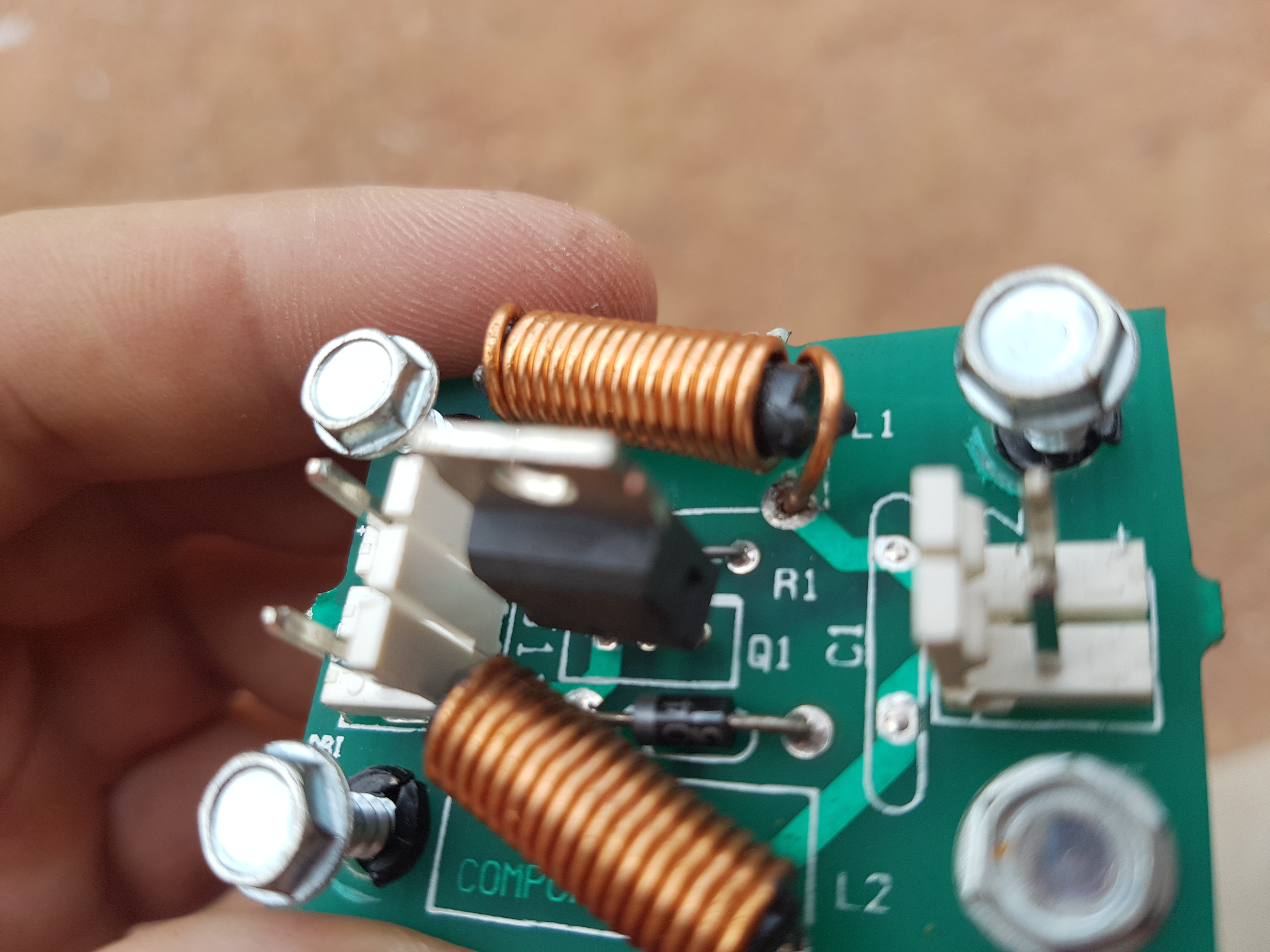
Had to repair an Indy with an error saying “Idol is Bad”, although when i went into the Idol test, it worked for a bit, and then stopped. Switch the machine off and back on, and it didn’t work at all. I lifted the playfield (while in the Idol test) and looked at the connections to the motor, which all looked good. Then had a look at the motor driver board and the inductor looked a bit suspect. When i pushed it, the idol would work. Removed the board, reflowed the solder around the leg of the component (after stripping the insulation off), and it worked perfectly.
Author Archives: Rob
Data East Lethal Weapon 3 flippers stop working when hot
Had a Lethal Weapon 3 (Data East) that after playing for 40 minutes or so, the flippers would go dead. Then you turn the machine off for 5 or 10 minutes and they would work for a while again..hmmmmm
I checked the voltages, and even when the flippers were not working, they had the correct voltage (50V) – also, in the switch test, the cabinet switches were working fine. So i knew the signal was getting to the CPU to fire the flippers, and that there was power at the flippers, so there must be something in the signal out of the CPU that was the issue.
I had a look at the CPU, and there is a relay (RY1) that is part of the flipper circuit. A gentle tap on the top of this, and the flippers would suddenly start working again!!! Replace the relay, and good to go.
Indiana Jones Idol Motor not working
The idol was a little intermittent on my Indiana Jones, and eventually stopped working. I swapped all sorts of components around between working machines with no luck. So i went back to the trusty manual and looked at the wiring diagram. As i was noticing how the idol motor was driven from the 8 drive PCB (an additional board to IJ, Star Trek and Twilight Zone), i wondered if any of the other components driven from that board worked.
Most of the others driven from these transistors are flashers, and none of them worked!! At least i narrowed down the problem now (after spending hours swapping all sorts of other boards and motors!). I then unplugged and replugged (also known as reseating) each connector going to this board. One by one, restarting the machine to see if the issue disappeared. Finally, i narrowed it down to the Z connector between J114 of the power driver board and J210 of the MPU. After lightly sanding this connector with some emery paper, the issue has not since reappeared.
Distorted sound WPC
I had an issue with a sound board that was working OK and then suddenly became very distorted – sounded like it was being played underwater, and most of the louder sounds were completely blown out.
I replaced a heap of capacitors without any luck. In the end, i replaced 5 more capacitors – i am unsure which one (or ones) made the difference as i changed them all before testing again. The ones i changed were:
C34 and C37 (one was a 47uF, the other 1uF – i don’t recall which was which)
C26,C27,C28,C29 (all 1uF)
Many of these were tantalum capacitors, but i replaced them with more readily available electrolytics. Anyway, the sound is back to completely normal now. If i come across this issue again, i will try and narrow it down to the exact capacitor!
Sound VERY loud and volume control not working
I grabbed a sound board out of one my project machines in the shed and installed the ROMs in it of my recently restored Fishtales (see the restorations page for details). Turned the machine on and the volume was extremely loud and unable to be turned down.
After stopping my ears bleeding, i started to look for the problem. The volume control is ‘electronic’ in that there is a non mechanical potentiometer at U5 (X9503) – it just is a small 8 legged IC. I removed the old one, and put a socket in and tried a new one…..No luck – still the same problem. Since i carefully desoldered the old one (with a vacuum desoldering station), i put it back in the socket and started to look elsewhere. There is a 47uF capacitor that connects to this potentiometer. Since i have a heap of spares, and they are cheap, i cut the old one out and put a replacement one in – and it all worked!
Not all repairs are this easy (or cheap), but hopefully this might help someone who may have a similar problem.
Monster Bash Front cabinet switches not working
Went out to look at a Monster Bash i had previously restored, as the start and launch buttons were not working on the machine.
The guy had replaced the bulb in the start button recently (i should have taken more notice of this!)
I normally start repairs with switch or lamp issues by determining if the problem is on the playfield, or on the CPU board. To do this, you go into the switch edges test, then remove the switch input plugs from the CPU, and bridge the pins across with a diode to simulate a switch signal going to the CPU. In this particular case, we got the switches to activate via this method. This tells us the problem is back from the CPU board itself (ie: a playfield wiring or switch issue).
Now the start and launch button are both on row 1 of the switch matrix, so this told me that the problem almost certainly has to be related and it was not two switches failing at the same time.
So we set the multimeter on buzz mode (to test continuity and see if we could find where the signal was disconnected (following the green/brown wire). We got continuity to the plumb bob tilt which is in the cabinet, plus all the switches on the playfield on this particular row of switches (row 1).
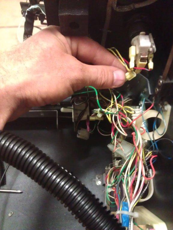
We also got continuity between the launch and start button, but not with any of the other switches in the row. We started to look at the plugs in the small board inside the front left of the cabinet and wondered if there was a dodgy connection. Eventually we tested continuity between one of the plugs and the start button – no continuity…….
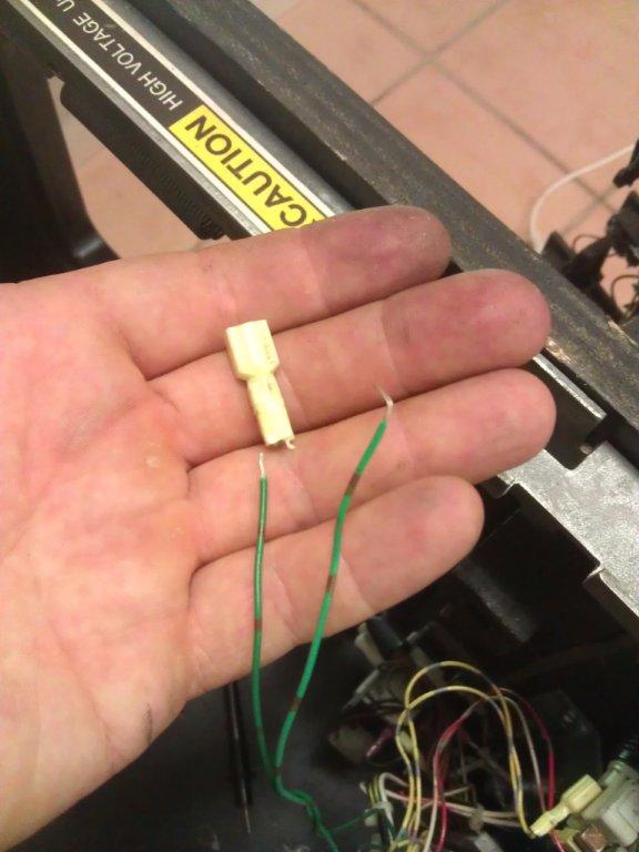
After inspecting the wire (it was only 150mm long) it all looked good, with no breaks or exposed sections, we determined it had to be the blade connector at the end. So we cut this off, replaced with a new one and everything worked! So what had happened, was the guy must have pulled a bit too hard on the wires rather than the plug going into the switch when he replaced the bulb, and the wires were still joined to each other, but not to the metal part of the connector – or they probably were not joined particularly well from the factory.
Wiring to the start button
The offending dodgy connector – now snipped off
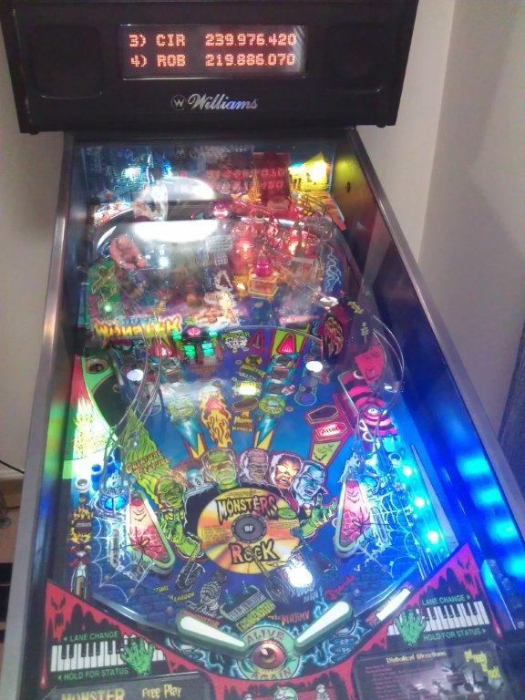
Game fully working – note how i knocked one of his high scores of in my test game!
Flame Polishing Pinball Ramps and Plastics
See the video below for a quick overview of flame polishing pinball ramps that i did a few years ago. Its really important to clean the ramps thoroughly, then polish will 1500 and 2000 wet/dry paper to take out any marks, after that (and you have double checked for no remaining ball trails), crack out the blowtorch and flame polish.
I find using a smaller soldering iron type blow torch is more forgiving as you have a it more time and can see it working, but you still need to be very careful as if you hold it in one spot too long the plastic will bubble and/or the ramp could warp.
Battery Corrosion
One of the most common problems on pinball machines is people forgetting to replace their batteries (located on one of the boards in the backbox of the machine).
The batteries then leak over time and eat away at the board and components, causing all sorts of nasty issues.
The best way to overcome this problem is to install a remotely mounted battery pack. This is a quite easy procedure if you have basic soldering skills. I will put a video up soon showing how to complete this essential modification.


